Bearing Manufacturer & Supplier
Specialize in ball bearings, roller bearings, thrust bearings, thin section bearings etc.
Everything You Should Know About Bearing Radial Clearance and Internal Clearance
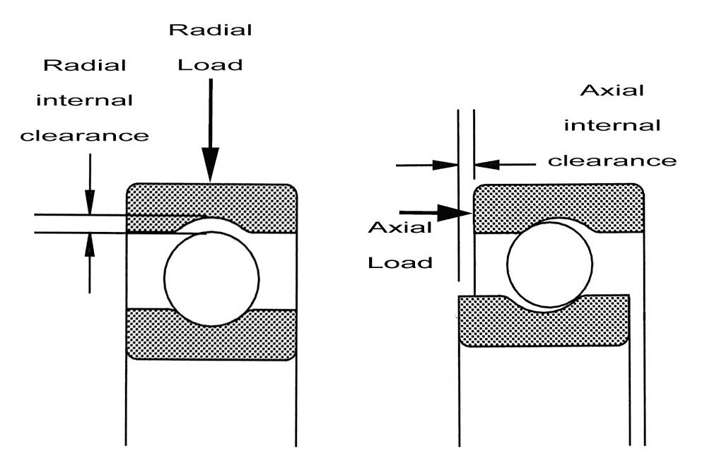
At first glance, ball bearings are relatively simple mechanical parts. However, analysis of their internal geometry reveals that they are very complex. For example, the conformity of the balls to the raceway, the radial clearance and the number of balls all affect the ability of a ball bearing to support loads under various conditions. Typically, ball and other rolling element bearings are designed and assembled with a slight internal looseness between the rolling elements (balls) and raceways. This looseness creates radial clearance and axial clearance in the bearing.
It should be noted that due to the nature of their design and construction, the internal geometry of needle, roller and tapered roller bearings is very different from that found in ball bearings. For example, tapered roller bearings are unique in that the clearance within the bearing is adjusted during assembly. Radial clearance and running bearing internal clearance are the most important of all rolling elements. In this Technical Information Sheet (TIS), the discussions of contact angle, deflection, end clearance and preload apply primarily to ball bearings.

Table of Contents
ToggleDefinition Of Radial clearance In A Ball Bearing
Radial clearance, or bearing internal clearance, is the internal radial looseness in a bearing and is the measured value of the total radial movement of the outer ring with respect to the inner ring in a plane perpendicular to the bearing axis. Ball bearings are assembled to radial clearance values depending upon the desired range. The radial clearance is determined by the actual raceway diameters and ball diameter.
Radial clearance can be verified on assembled bearings using specially designed gages. When measuring the radial clearance, the bearing is subjected to a standard gage load to ensure full contact between all the bearing components. With regard to miniature and thin section bearings under such a load, the measured value is larger than the stated value for radial clearance. This is due to elastic deformation. Compensation factors are used in these cases.

Definition Of Axial clearance In A Ball Bearing
Axial, or end clearance, is the maximum relative axial movement of the inner ring with respect to the outer ring. The end clearance is directly related to the radial clearance of the ball bearing. In most part numbering systems axial clearance is not normally specified.
There is often confusion with “looseness” and precision level. Radial clearance is specified independently of ABEC tolerance classes for rings. With ball bearings, in most cases, the internal looseness should be removed in the assembly process by applying an axial preload across the pair of bearings. This can be accomplished with shims, springs, take up nuts, and/or other assembly techniques. Axial preload is also an important design parameter that affects both performance and life. Preload is explained in further detail in a separate Technical Information Sheet (TIS).

Contact Angle In A Ball Bearing
When ball bearings are axially preloaded a contact angle is established. The contact angle is the angle between a plane perpendicular to the bearing axis and a line joining the two contact points between the ball and the inner and outer raceways. The initial contact angle is the contact angle when the bearing is subjected to the minimal axial force or load necessary to remove the looseness resulting from the radial clearance. Additional applied axial loads will increase the contact angle further. The greater the value of radial clearance in the bearing, the greater the resulting contact angle will be.
In most bearing applications, radial clearance, from a functional point of view, is critical than axial clearance. As a result, it has become the standard purchasing specification.

General Design Considerations:
The selection of the radial clearance value in a specific bearing application is an important design consideration. As described previously, radial clearance directly affects the contact angle and axial, or end, clearance of the bearing. In addition, in operation it is an important factor that has a significant influence on other factors such as noise, vibration, heat, stress, deflection, load distribution and fatigue life.
Fitting:
A looser or greater value of radial clearance should be selected when the bearing is mounted using interference fits. The radial clearance in the bearing is reduced after mounting due to deformation of the inner or outer rings. With miniature bearings having very thin cross section rings, the radial clearance is reduced by approximately 80% of the actual amount of interference. The radial clearance after mounting is the primary design consideration. Therefore, a tolerance study of the mating components should be completed and compensation for the interference at maximum material condition must be made. For maximum life, a positive clearance after mounting is desired.
Loading:
When a ball bearing is subjected to thrust loading, a higher contact angle will result in reduced ball to raceway stresses. Greater values of radial clearance result in higher values of contact angle. Under these conditions, this will provide longer bearing life, lower torque, and less axial deflection. In a pure thrust situation, a 15° increase in contact angle can result in over a 70% reduction in contact stress (ball-to-raceway).
When a ball bearing is subjected to pure radial loads (or radial load with low axial load), lower radial clearance is normally recommended. This distributes the load over a greater number of balls. However, particularly with miniature bearings, bearings with low radial clearance should not be subjected to interference fits. This can result in negative clearance and drastically reduce life.
Misalignment And Positioning:
Higher values of radial clearance allow for greater misalignment and should be selected in cases where there is a high degree of shaft deflection. It should be noted, although a ball bearing has the ability to compensate (around 1° or less), misalignment greatly reduces bearing life. However, in cases with light loads, the impact of minor misalignment may be tolerable.
Tighter values of radial clearance will of course control and restrict radial movement.
When axial positioning must be controlled or end clearance of “zero” is desired, it is recommended that the end clearance be removed by applying axial preload via shims, washers, or other assembly methods. Duplex bearings should be considered as well. It is not advisable to use low values of radial clearance to control end clearance.
Temperature:
When a high temperature gradient exists between the inner and outer rings a looser radial clearance is recommended.
Speed:
As mentioned previously, high values of radial clearance result in high values of contact angle. When a bearing is rotating, the set of balls (or ball complement) is rotating about the pitch circle of the bearing, each ball is rotating about its own axis, and gyratory moments are acting upon the balls. The magnitude of the gyratory moment is related to the contact angle. As rotational speed increases, the gyratory forces acting on the balls increases and there is sliding action between the balls and the raceways. This slippage results in lubricant film failure, increased heat, and potential premature failure. The balance between the benefits of contact angle reducing stress must be weighed against the potential for lubricant failure due to ball slippage.
Specifying Radial clearance:
It is not practical, or perhaps even possible, to produce a group of bearings that all have the exact same amount of radial clearance. This is because all of the features of the bearing components (inner ring raceway, outer ring raceway, and balls) that effect radial clearance, have manufacturing tolerances associated with them. Manufacturers measure and sort the bearing rings and balls so that they can be “matched” during the assembly process to achieve a specific range of radial clearance for a group (or manufacturing lot) of bearings.
There are several ways to specify radial clearance. Radial clearance specifications are usually manufacturer dependent. Complete part number descriptions are detailed in a separate Technical Information Sheet (TIS). AUB specifies radial clearance as follows:
For metric design ball bearings (miniature and instrument) with a bore diameter of less than 10 mm.
Clearance Symbol | MC1 | MC2 | MC3 | MC4 | MC5 | MC6 | |
Actual Clearance in uM | min | 0 | 3 | 5 | 8 | 13 | 20 |
max | 5 | 8 | 10 | 13 | 20 | 28 | |
Actual Clearance in inches | min | 0 | 0.0001 | 0.0002 | 0.0003 | 0.0005 | 0.0008 |
max | 0.0002 | 0.0003 | 0.0004 | 0.0005 | 0.0008 | 0.0011 | |
For inch design ball bearings (miniature and instrument) with a bore diameter of less than 10 mm.
AST CODE | Actual Radial clearance Range in Inches | Classification |
K13 or P13 | .0001 to .0003 | Tight |
K25 or P25 | .0002 to .0005 | Normal |
K58 or P58 | .0005 to .0008 | Loose |
K811 or P811 | .0008 to .0011 | Extra Loose |
For deep groove ball bearings with a bore diameter of 10 mm or greater the following tables are used.
Internal Clearance For Radial Deep Grove Ball Bearings In Micrometers

Internal Clearance For Radial Deep Grove Ball Bearings In Inches (.0001”)


